Z-Buffer or Depth-Buffer method
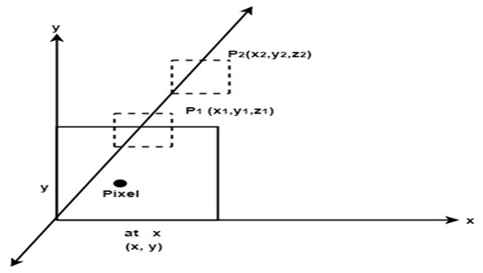
It is also called a Depth Buffer Algorithm. Depth buffer algorithm is simplest image space algorithm. For each pixel on the display screen, we keep a record of the depth of an object within the pixel that lies closest to the observer. In addition to depth, we also record the intensity that should be displayed to show the object. Depth buffer is an extension of the frame buffer. Depth buffer algorithm requires 2 arrays, intensity and depth each of which is indexed by pixel coordinates (x, y).
Algorithm
For all pixels on the screen, set depth [x, y] to 1.0 and intensity [x, y] to a background value.
For each polygon in the scene, find all pixels (x, y) that lie within the boundaries of a polygon when projected onto the screen. For each of these pixels:
(a) Calculate the depth z of the polygon at (x, y)
(b) If z < depth [x, y], this polygon is closer to the observer than others already recorded for this pixel. In this case, set depth [x, y] to z and intensity [x, y] to a value corresponding to polygon's shading. If instead z > depth [x, y], the polygon already recorded at (x, y) lies closer to the observer than does this new polygon, and no action is taken.
3. After all, polygons have been processed; the intensity array will contain the solution.
4. The depth buffer algorithm illustrates several features common to all hidden surface algorithms.
5. First, it requires a representation of all opaque surface in scene polygon in this case.
6. These polygons may be faces of polyhedral recorded in the model of scene or may simply represent thin opaque 'sheets' in the scene.
7. The IInd important feature of the algorithm is its use of a screen coordinate system. Before step 1, all polygons in the scene are transformed into a screen coordinate system using matrix multiplication.
Limitations of Depth Buffer
- The depth buffer Algorithm is not always practical because of the enormous size of depth and intensity arrays.
- Generating an image with a raster of 500 x 500 pixels requires 2, 50,000 storage locations for each array.
- Even though the frame buffer may provide memory for intensity array, the depth array remains large.
- To reduce the amount of storage required, the image can be divided into many smaller images, and the depth buffer algorithm is applied to each in turn.
- For example, the original 500 x 500 faster can be divided into 100 rasters each 50 x 50 pixels.
- Processing each small raster requires array of only 2500 elements, but execution time grows because each polygon is processed many times.
- Subdivision of the screen does not always increase execution time instead it can help reduce the work required to generate the image. This reduction arises because of coherence between small regions of the screen.
Discussion & Queries (<$I18NNumComments$>):
<$CommentPager$>
- <$I18NAtCommentTimeWithPermalink$>, <$I18NCommentAuthorSaid$>
<$CommentPager$>
<$BlogCommentBody$>
<$BlogCommentDeleteIcon$>