LAN (Local Area Network) standards are specifications and protocols that define how devices communicate within a limited geographical area, typically within a single building or campus. These standards ensure compatibility and interoperability among different network devices. Some of the most common LAN standards include:
Ethernet: Ethernet is the most widely used LAN technology. It defines the physical and data link layers of the OSI model. The IEEE 802.3 standard specifies Ethernet standards, which include various data rates such as 10 Mbps (10BASE-T), 100 Mbps (100BASE-TX), 1 Gbps (1000BASE-T), 10 Gbps (10GBASE-T), and beyond.
Wi-Fi (IEEE 802.11): Wi-Fi is a wireless LAN standard that enables devices to connect to a network without physical cables. It operates in various frequency bands and provides different data rates, with the most common ones being 802.11n, 802.11ac, and 802.11ax (Wi-Fi 6).
Token Ring (IEEE 802.5): Token Ring is a LAN technology that uses a token-passing mechanism to control access to the network. It operates at speeds of 4 or 16 Mbps and was more prevalent in the past but has largely been replaced by Ethernet.
Fiber Distributed Data Interface (FDDI): FDDI is a LAN standard that uses fiber optic cables for high-speed data transmission. It operates at speeds of up to 100 Mbps and is primarily used in backbone networks.
Power over Ethernet (PoE): PoE is a standard that allows electrical power to be transmitted along with data on Ethernet cables. It eliminates the need for separate power cables, simplifying network installations, and is commonly used to power devices such as IP phones, wireless access points, and surveillance cameras.
HomePlug (IEEE 1901): HomePlug is a set of standards that enable power lines to be used for data transmission in home networking applications. It allows devices to communicate over existing electrical wiring within a building.
Network switching is the process of forwarding data frames or packets from one port to another leading to data transmission from source to destination. Data link layer is the second layer of the Open System Interconnections (OSI) model whose function is to divide the stream of bits from physical layer into data frames and transmit the frames according to switching requirements. Switching in data link layer is done by network devices called bridges.
Bridges
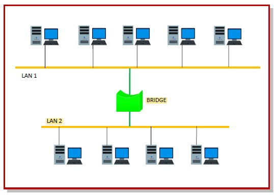
A data link layer bridge connects multiple LANs (local area networks) together to form a larger LAN. This process of aggregating networks is called network bridging. A bridge connects the different components so that they appear as parts of a single network.
The following diagram shows connection by a bridge −

Switching by Bridges
When a data frame arrives at a particular port of a bridge, the bridge examines the frame’s data link address, or more specifically, the MAC address. If the destination address as well as the required switching is valid, the bridge sends the frame to the destined port. Otherwise, the frame is discarded.
The bridge is not responsible for end to end data transfer. It is concerned with transmitting the data frame from one hop to the next. Hence, they do not examine the payload field of the frame. Due to this, they can help in switching any kind of packets from the network layer above.
Bridges also connect virtual LANs (VLANs) to make a larger VLAN.
If any segment of the bridged network is wireless, a wireless bridge is used to perform the switching.
There are three main ways for bridging −
- simple bridging
- multi-port bridging
- learning or transparent bridging
Transparent Bridge
A transparent bridge is a common type of bridge that observes incoming network traffic to identify media access control (MAC) addresses. These bridges operate in a way that is transparent to all the network's connected hosts.A transparent bridge records MAC addresses in a table that is much like a routing table and evaluates that information whenever a packet is routed toward its location. A transparent bridge may also combine several different bridges to better inspect incoming traffic. Transparent bridges are implemented primarily in Ethernet networks.
Transparent bridges maintain a list of MAC addresses, as do routers, based on all the received frames' source data-link MAC addresses. These tables are used for address look-up while forwarding a frame.
Transparent bridges save and maintain the source-route addresses of incoming frames by listening to all the connected bridges and hosts. They use a transparent bridging algorithm to a accomplish this. The algorithm has five parts:
- Learning
- Flooding
- Filtering
- Forwarding
- Avoiding loops
For example, consider three hosts, A, B and C, and a bridge with three ports. Host A is connected to Bridge Port 1, Host B is connected to Bridge Port 2 and Host C is connected to Bridge Port 3. Host A sends a frame to the bridge that is addressed to Host B. The bridge checks the frame's source address and creates an address and port number entry for Host A in its forwarding table. The bridge then examines the frame's destination address, but does not find it in its forwarding table. As a result, the bridge sends the frame to all the other ports (2 and 3). This is called flooding. The frame is then received by Host B and Host C, which also check the destination address. Host B recognizes a destination address match and sends a response to Host A.


No comments:
Post a Comment