Paging In OS with Examples
Paging is a technique of Non-Contiguous where one process can reside at different locations of main memory. So, spanning is totally possible. In this post we will see all bout paging with examples.
Need of Paging
The main disadvantage in Contiguous Dynamic Partitioning was External fragmentation. Although, External fragmentation may remove by Compaction but it makes the system inefficient.
In paging, external fragmentation was totally remove without compaction.
Explain with Example
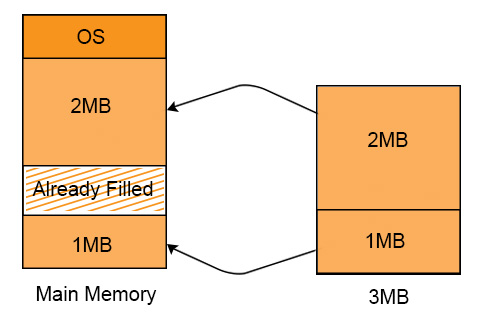
P1 requires 3 MB space to load in the main memory. We have two holes of 2MB and 1MB respectively available at different locations in main memory. And still Process 1 can load successfully. It is because of non-contiguous memory allocation.
Concept of Paging
In which processes are organized in equal size blocks called pages and the main memory is organized in equal sized blocks called frames.
Pages at secondary memory and frames at main memory both have the same size. As, CPU does not generate absolute address. But it generates the logical address.
But the actual data required to CPU present in main memory. Physical address is requiring to access actual data in main memory. For this purpose, system use the MMU. MMU further use the Page table. Every process has its own page table.
Entries of page table of each process = total no of pages of that process
Paging is a technique in which the main memory is organized in equal sized blocks. These blocks also known as pages. In this technique, the address of occupied pages of physical memory is stored in a table, which is known as page table.
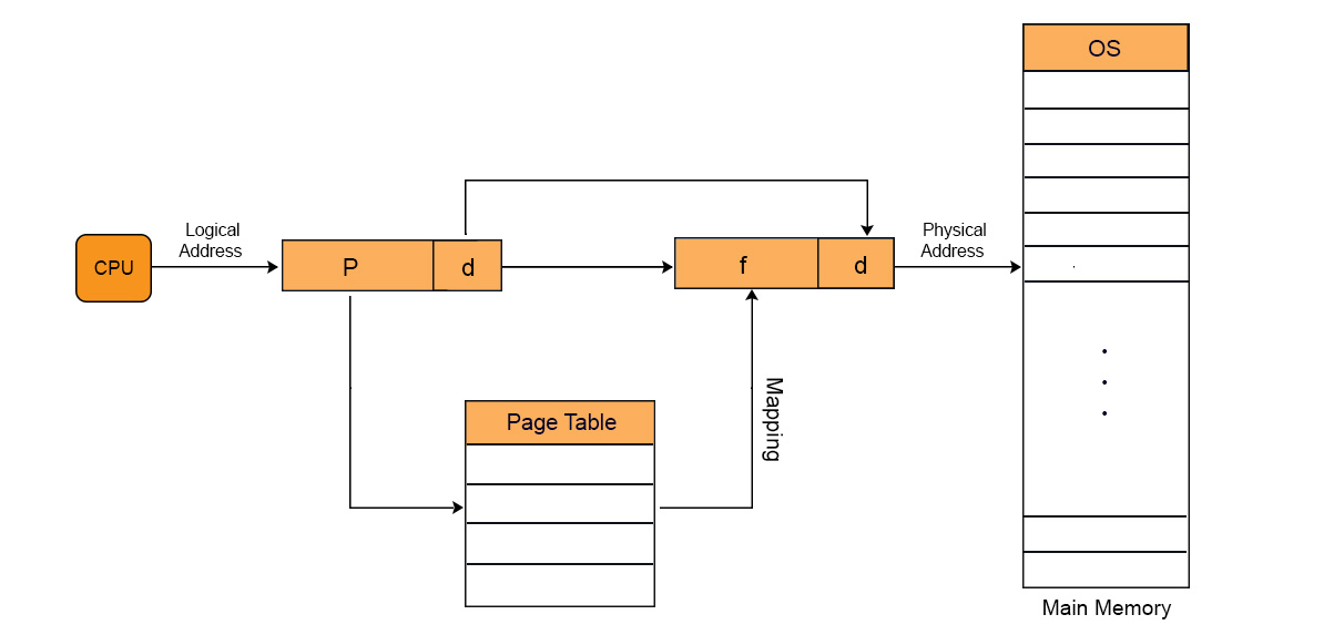
Through Paging, OS can get the physical memory location without specifying the lengthy memory address in the instruction. In this technique, the virtual address is use to map the physical address of the data. The length of virtual address is specified in the instruction and is smaller than physical address of the data. It consists of two different numbers, first number is the address of page which is known as virtual page in the page table. Second number is the offset value of the actual data in the page. Let explain with diagram
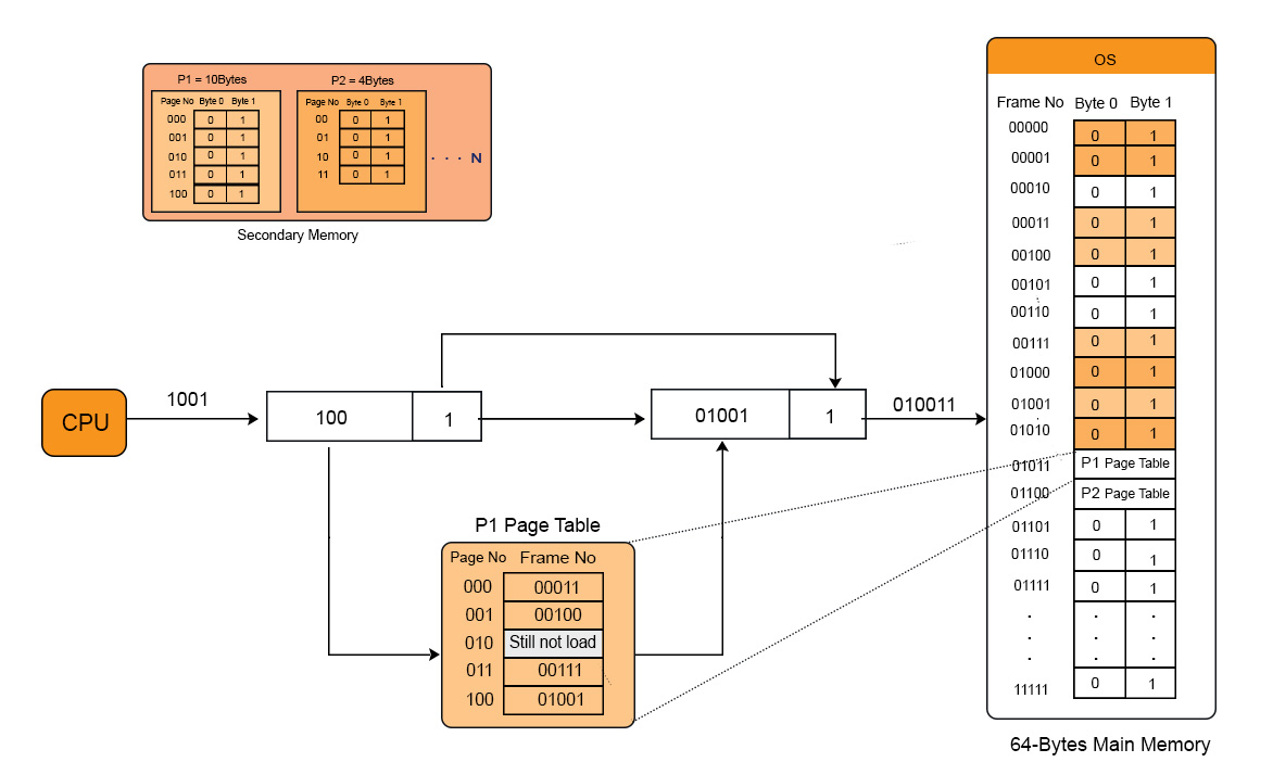
Lets Explain with example.
Multilevel Paging in OS
Entry of each page of a process is recorded into its page table. If page table size is greater than its frame then OS further divide the page table into equal frame size. So, that page table could easily be accommodate into the frame. it is all multilevel paging in OS.
Page Table Base Register value is stored in Outer most table of that process. We move outer most to inner most table to find the required address.
Important.
In the same way, if the size of second level page table is greater than frame size then we again divided 2 level page table into equal frame size and third level page table is generated and so on.
Multilevel paging with example
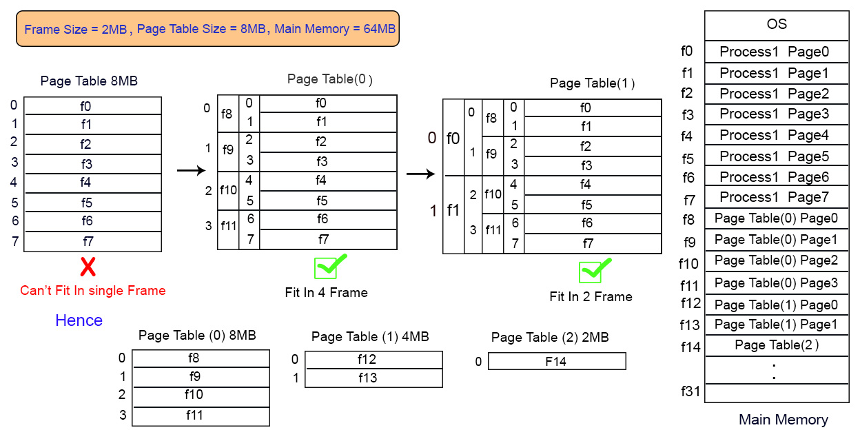
If there is a process of 8 pages and its page table size is 8MB while the frame size of main memory is 2MB. Then page table cannot fit into single frame so we have to load this table into multiple frames.
As size of Page table is 8MB so divide it into 4 equal page tables of 2MB each. These 4 page tables are loaded into different frames as shown in diagram.
Inverted Page Table
Need of Inverted Page table
Most of the Operating Systems use a separate page table for each process as in normal paging. In normal paging if there are 100 process then 100 will be the page tables in main memory. Sometimes when a process size is very large then its page table size also increases considerably. Through inverted page table, the overhead of storing an individual page table for each process is removed. A global page table is used which is utilized by all processes.
Example: If A process size is 2 GB with Page size = 512 Bytes and page table entry size is 4 Bytes, then
- Number of pages in the process = 2 GB / 512 B = 222
- Page Table Size = 222 * 22 = 224 bytes
If multiple processes running simultaneously in an OS with large sizes, then a considerable amount of memory is occupied by page tables only.
Various efforts are made to utilize the memory efficiently and to maintain a good balance in the level of multi-programming and efficient CPU utilization.
Working
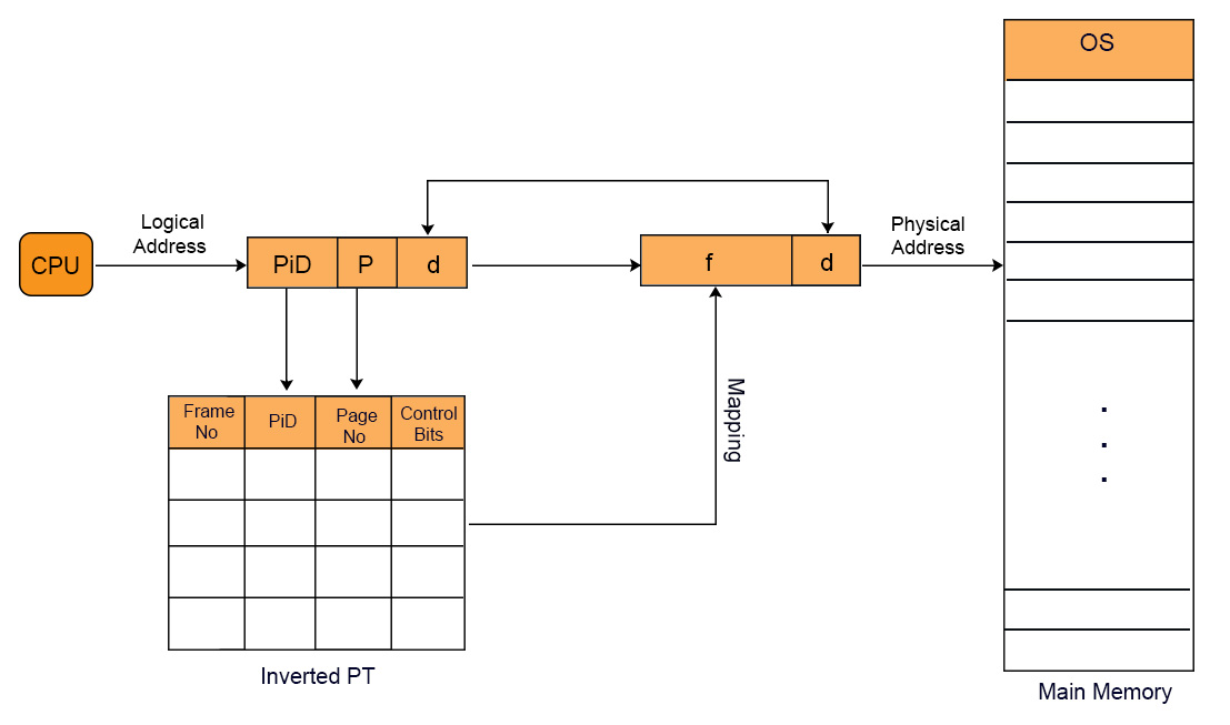
In inverted page table indexing is done with frame numbers instead of the logical page number. Each entry in the page table contains the following fields.
- Frame No: It specifies the Frame where the page no is actually present in main memory
- Page number:It specifies the page number which is required.
- Process id: An inverted page table contains pages of all the processes in execution. So page No may be same of different process but Process Id of each process is unique. Through Process ID we get the desired page of that process.
- Control bits –These bits are used to store paging table entry information. These include the valid/invalid bit, protection, dirty bit, reference bits, and other information bit.
- Chained pointer:It is possible when two or more processes share some part of main memory. In simple words, when two or more logical pages need to map to same Page Table Entry then a chaining pointer is used.
No of frames in main memory = No of entries in Inverted page table
Example
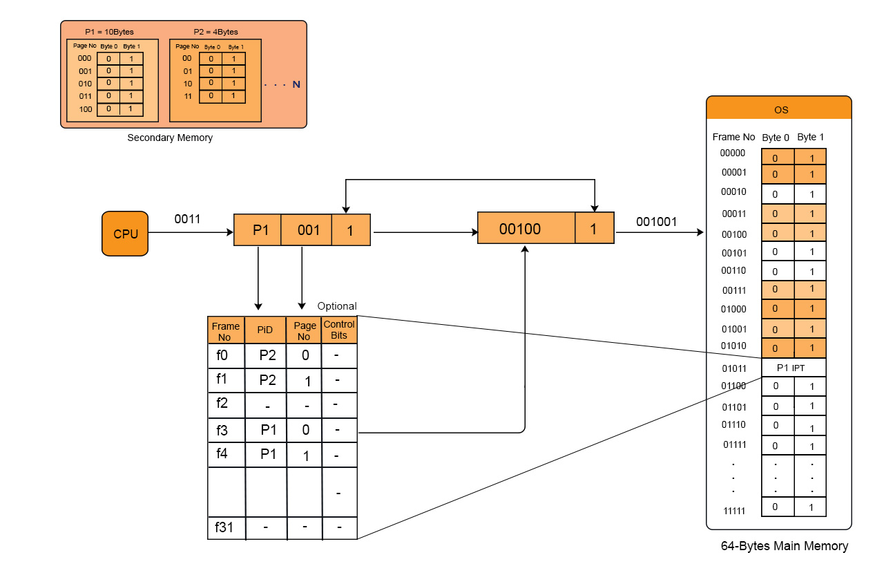
We have to linear search as we want to find page 2 of process 3 then
The logical address generated by the CPU contains Process ID, Page No, and Page Offset.
Through searching in Inverted Page Table, Process ID and Page No of logical address are compared with Process ID and Page No.
If match found then its corresponding frame number is obtained from page table entry otherwise page fault is occur and Demand paging comes into picture.
Note: No. of Entries in Inverted page table = No. of frames in Physical address Space
Advantages and Disadvantages:
- Reduced memory space
- Longer Search time
Translation Look aside Buffer (TLB)
You must have the concept of paging before to learn Translation lookaside Buffer. But In term of paging, we have to access the main memory twice or more for accessing a page.
- Once when we get the Page table from main memory.
- And second when we get the particular page from main memory of corresponding frame.
In this way, main memory is accessed twice in paging and even more than twice while using multilevel paging. So it was time consuming.
This problem is overcome by using TLB. TLB is hardware component and is a part of MMU. TLB works like Cache Memory. It Exists within CPU casing and in some cases it found on IC chip.
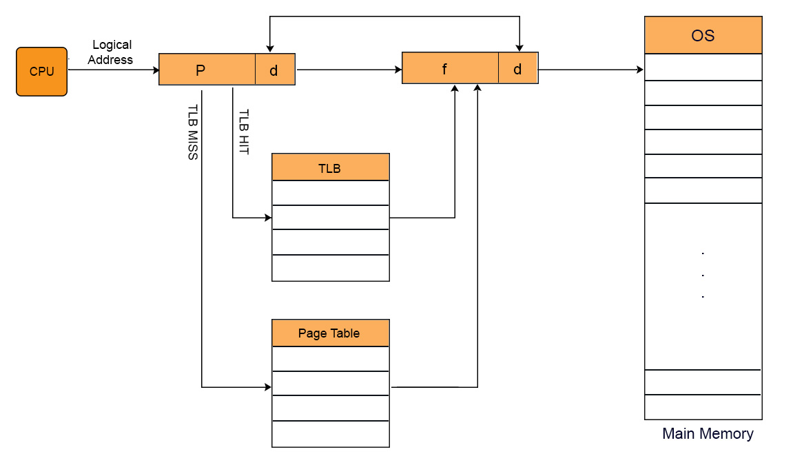
Working of TLB
when CPU generates virtual address of any page then it first look that particular page in TLB.In case of TLB hit, data is directly accessed from main memory without accessing the main memory twice or more.
In case of TLB miss, OS have to repeat the concept of paging again to find required page. After getting that particular page from main memory, it first loaded into TLB . So that, if CPU demand for this page in later, then it could be easily access from TLB, without repeating the paging.
TLB contains Tag (Process No + Process ID) and Frame. Page Number is compared with Tag .As, it contains pages of only running processes. So, Process ID is not compulsory. Lets look at TLB diagram given under,
TLB only contains the pages that are accessible to the current process. If process A is currently running, then TLB will contains only the translation (Logical to physical address) for the pages of process A. If process B is currently running then there will be no page of Process A in TLB and vice versa.
When CPU switches from one process to another process then TLB of currently running process is also cleared. This process is also known as flushing of TLB.
Translation Look aside Buffer VS Cache Memory
Both TLB and Cache memory are hardware’s exist within the CPU chip. The basic purpose of both these components is to access faster data. The major differences between TLB and Cache are.
| TLB | Cache Memory |
| 1. TLB is required only when Virtual Memory is used by CPU. | 1. Cache memory is the basic component of modern system. |
| 2. TLB is used to speed up address translation for Virtual memory so that page table is not need to access for every address. | 2. CPU Cache is used to speed up main memory access. Most recently and most frequently data is present in Cache memory. If data is found in Cache the there is no need to go for RAM. |
| 3. TLB performs operations at the time of address translation by MMU. | 3. CPU cache performs operations at the time of memory access by CPU. |
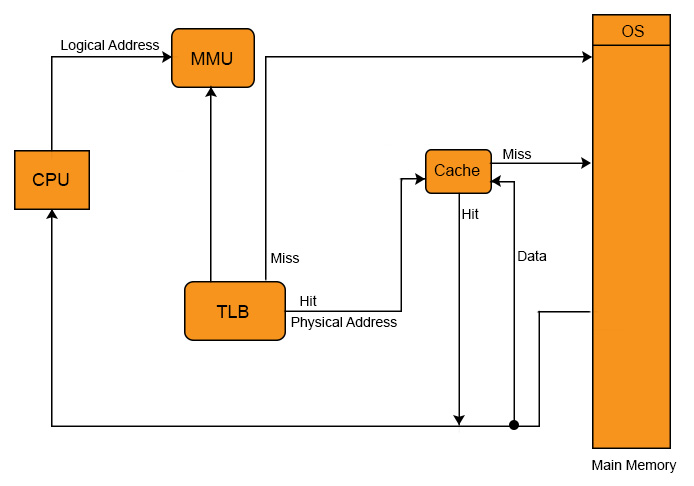
Cache and TLB working Model
In fact, in all modern CPU’s having the all Cache levels and TLB as well. Working Model of Cache and TLB with diagram,
Multiple TLBs
Same like the caches, TLBs also have multiple levels. Now a days CPU has multiple TLB’s. CPU may have three (ITLB1, DTLB1, TLB2) or four TLBs. These TLB’s s are differing in Speed and capacity from it’s others types.
Question on TLB
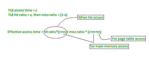
Effective Memory Access Time Calculation Formula’s
TLB_hit_time: = TLB_search_time + memory_access_time
TLB_miss_time: = TLB_search_time + memory_access_time + memory_access_time
EMAT: = hit_ratio * TLB_hit_time + (1- hit-ratio) * (TLB_miss_time)
OR
EMAT: = hit_ratio * (TLB_search_time + memory_access_time) + (1 – hit_ratio) * (TLB_search_time + 2*memory_access-time)
If hit ratio is denoted By “P”, TLB search time is “t” and TLB memory access time is “m” then EMAT will be.
EMAT = P(t+m) + (1-P)(t+2m)
Question: A paging scheme using TLB. TLB access time 10ns and main memory access time takes 50ns. What is effective memory access time (in ns) if TLB hit ratio is 90% and there is no page fault.
Solution
EMAT: = hit_ratio * (TLB_search_time + memory_access_time) + (1 – hit_ratio) * (TLB_search_time + 2*memory_access-time)
= 90%(10+50) +10%(10+2(50))
=65ns


No comments:
Post a Comment