What is a Carry Look-ahead Adder?
A digital computer must contain circuits which can perform arithmetic operations such as addition, subtraction, multiplication, and division. Among these, addition and subtraction are the basic operations whereas multiplication and division are the repeated addition and subtraction respectively.
To perform these operations ‘Adder circuits’ are implemented using basic logic gates. Adder circuits are evolved as Half-adder, Full-adder, Ripple-carry Adder, and Carry Look-ahead Adder.
Among these Carry Look-ahead Adder is the faster adder circuit. It reduces the propagation delay, which occurs during addition, by using more complex hardware circuitry. It is designed by transforming the ripple-carry Adder circuit such that the carry logic of the adder is changed into two-level logic.
4-Bit Carry Look-ahead Adder
In parallel adders, carry output of each full adder is given as a carry input to the next higher-order state. Hence, these adders it is not possible to produce carry and sum outputs of any state unless a carry input is available for that state.
So, for computation to occur, the circuit has to wait until the carry bit propagated to all states. This induces carry propagation delay in the circuit.

Consider the 4-bit ripple carry adder circuit above. Here the sum S3 can be produced as soon as the inputs A3 and B3 are given. But carry C3 cannot be computed until the carry bit C2 is applied whereas C2 depends on C1. Therefore to produce final steady-state results, carry must propagate through all the states. This increases the carry propagation delay of the circuit.
The propagation delay of the adder is calculated as “the propagation delay of each gate times the number of stages in the circuit”. For the computation of a large number of bits, more stages have to be added, which makes the delay much worse. Hence, to solve this situation, Carry Look-ahead Adder was introduced.
To understand the functioning of a Carry Look-ahead Adder, a 4-bit Carry Look-ahead Adder is described below.

In this adder, the carry input at any stage of the adder is independent of the carry bits generated at the independent stages. Here the output of any stage is dependent only on the bits which are added in the previous stages and the carry input provided at the beginning stage. Hence, the circuit at any stage does not have to wait for the generation of carry-bit from the previous stage and carry bit can be evaluated at any instant of time.
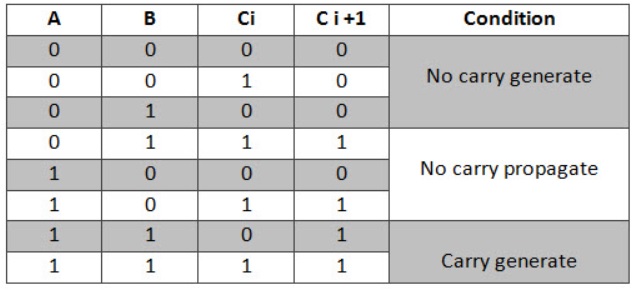
Truth Table of Carry Look-ahead Adder
Consider two 4-bit binary numbers A3A2A1A0 and B3B2B1B0 are to be added.
Mathematically, the two numbers will be added as-

From here, we have-
C1 = C0 (A0 ⊕ B0) + A0B0
C2 = C1 (A1 ⊕ B1) + A1B1
C3 = C2 (A2 ⊕ B2) + A2B2
C4 = C3 (A3 ⊕ B3) + A3B3
For simplicity, Let-
- Gi = AiBi where G is called carry generator
- Pi = Ai ⊕ Bi where P is called carry propagator
Then, re-writing the above equations, we have-
C1 = C0P0 + G0 ………….. (1)
C2 = C1P1 + G1 ………….. (2)
C3 = C2P2 + G2 ………….. (3)
C4 = C3P3 + G3 ………….. (4)
Now,
- Clearly, C1, C2 and C3 are intermediate carry bits.
- So, let’s remove C1, C2 and C3 from RHS of every equation.
- Substituting (1) in (2), we get C2 in terms of C0.
- Then, substituting (2) in (3), we get C3 in terms of C0 and so on.
Finally, we have the following equations-
- C1 = C0P0 + G0
- C2 = C0P0P1 + G0P1 + G1
- C3 = C0P0P1P2 + G0P1P2 + G1P2 + G2
- C4 =C0P0P1P2P3 + G0P1P2P3 + G1P2P3 + G2P3 + G3
These equations are important to remember.
These equations show that the carry-in of any stage full adder depends only on-
- Bits being added in the previous stages
- Carry bit which was provided in the beginning
It can be observed from the equations that carry Ci+1 only depends on the carry C0, not on the intermediate carry bits.
Trick To Memorize Above Equations-
As an example, let us consider the equation for generating carry bit C2.
There are three possible reasons for generation of C2 as depicted in the following picture-

In the similar manner, we can write other equations as well very easily.
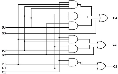
Implementation Of Carry Generator Circuits-
The above carry generator circuits are usually implemented as-
- Two level combinational circuits.
- Using AND and OR gates where gates are assumed to have any number of inputs.
Implementation Of C1–
- The carry generator circuit for C1 is implemented as shown below.
- It requires 1 AND gate and 1 OR gate.
C1 = C0P0 + G0

Implementation Of C2–
- The carry generator circuit for C2 is implemented as shown below.
- It requires 2 AND gates and 1 OR gate.
C2 = C0P0P1 + G0P1 + G1

Implementation Of C3 & C4–
Similarly, we implement C3 and C4.
- Implementation of C3 uses 3 AND gates and 1 OR gate.
- Implementation of C4 uses 4 AND gates and 1 OR gate.
Total number of gates required to implement carry generators (provided carry propagators Pi and carry generators Gi) are-
- Total number of AND gates required for addition of 4-bit numbers = 1 + 2 + 3 + 4 = 10.
- Total number of OR gates required for addition of 4-bit numbers = 1 + 1 + 1 + 1 = 4.
General Formula-
The following formula is used to calculate number of gates required for evaluating all carry bits-
For a n-bit carry look ahead adder to evaluate all the carry bits, it requires-
|
Circuit Diagram
The above equations are implemented using two-level combinational circuits along with AND, OR gates, where gates are assumed to have multiple inputs.
The Carry Look-ahead Adder circuit fro 4-bit is given below.
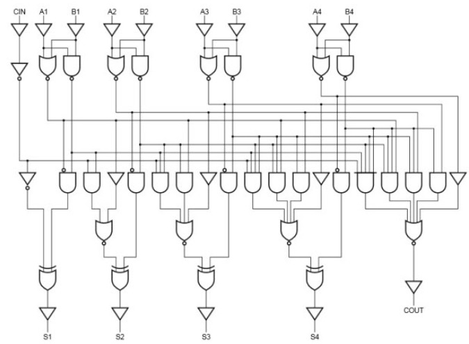
8-bit and 16-bit Carry Look-ahead Adder circuits can be designed by cascading the 4-bit adder circuit with carry logic.
Advantages of Carry Look Ahead Adder-
The advantages of carry look ahead adder are-
- It generates the carry-in for each full adder simultaneously.
- It reduces the propagation delay.
Disadvantages of Carry Look Ahead Adder-
The disadvantages of carry look ahead adder are-
- It involves complex hardware.
- It is costlier since it involves complex hardware.
- It gets more complicated as the number of bits increases.
Applications
High-speed Carry Look-ahead Adders are used as implemented as IC’s. Hence, it is easy to embed the adder in circuits. By combining two or more adders calculations of higher bit boolean functions can be done easily. Here the increase in the number of gates is also moderate when used for higher bits.
For this Adder there is a tradeoff between area and speed. When used for higher bit calculations, it provides high speed but the complexity of the circuit is also increased thereby increasing the area occupied by the circuit. This adder is usually implemented as 4-bit modules which are cascaded together when used for higher calculations. This adder is costlier compared to other adders.
For boolean computation in computers, adders are being used regularly. Charles Babbage implemented a mechanism for anticipating the carry bit in computers, to reduce the delay caused by the ripple carry adders. While designing a system, the speed of computation is the highest deciding factor for a designer. In 1957, Gerald B. Rosenberger patented the modern Binary Carry Look-ahead Adder. Based on the analysis of gate delay and simulation, experiments are being conducted to modify the circuit of this adder to make it even faster. For an n-bit carry look-ahead adder, what is the propagation delay, when given a delay of each gate is 20?


No comments:
Post a Comment