Congestion control refers to the techniques used to control or prevent congestion. Congestion control techniques can be broadly classified into two categories:
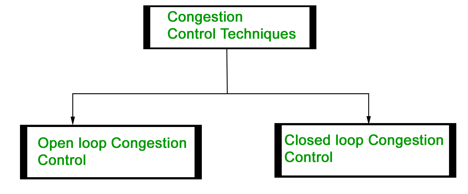
Open Loop Congestion Control
Open loop congestion control policies are applied to prevent congestion before it happens. The congestion control is handled either by the source or the destination.
Policies adopted by open loop congestion control –
- Retransmission Policy :It is the policy in which the retransmission of the packets are taken care. If the sender feels that a sent packet is lost or corrupted, the packet needs to be retransmitted. This transmission may increase the congestion in the network.To prevent congestion, retransmission timers must be designed to prevent congestion and also able to optimize efficiency.
- Window Policy :The type of window at the sender side may also affect the congestion. Several packets in the Go-back-n window are resent, although some packets may be received successfully at the receiver side. This duplication may increase the congestion in the network and make it worse.Therefore, a Selective repeat window should be adopted as it sends the specific packet that may have been lost.
- Discarding Policy :A good discarding policy adopted by the routers is that the routers may prevent congestion and at the same time partially discards the corrupted or less sensitive package and also able to maintain the quality of a message.In case of audio file transmission, routers can discard less sensitive packets to prevent congestion and also maintain the quality of the audio file.
- Acknowledgment Policy :Since acknowledgments are also part of the load in the network, the acknowledgment policy imposed by the receiver may also affect congestion. Several approaches can be used to prevent congestion related to acknowledgment.The receiver should send an acknowledgment for N packets rather than sending an acknowledgment for a single packet. The receiver should send an acknowledgment only if it has to send a packet or a timer expires.
- Admission Policy :In admission policy a mechanism should be used to prevent congestion. Switches in a flow should first check the resource requirement of a network flow before transmitting it further. If there is a chance of a congestion or there is a congestion in the network, router should deny establishing a virtual network connection to prevent further congestion.
Closed Loop Congestion Control
- Backpressure :Backpressure is a technique in which a congested node stop receiving packet from upstream node. This may cause the upstream node or nodes to become congested and rejects receiving data from above nodes. Backpressure is a node-to-node congestion control technique that propagate in the opposite direction of data flow. The backpressure technique can be applied only to virtual circuit where each node has information of its above upstream node.
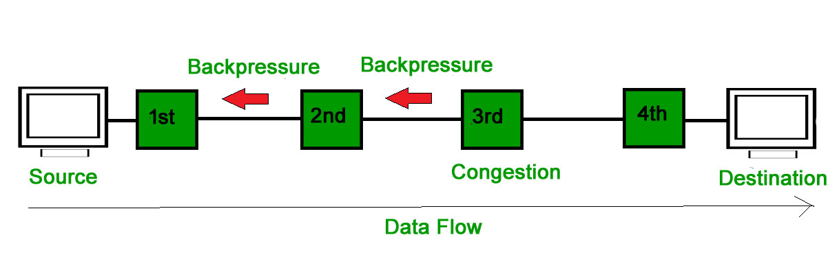
- In above diagram the 3rd node is congested and stops receiving packets as a result 2nd node may be get congested due to slowing down of the output data flow. Similarly 1st node may get congested and informs the source to slow down.
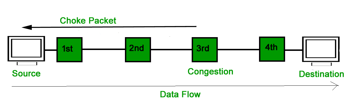
- Choke Packet Technique :Choke packet technique is applicable to both virtual networks as well as datagram subnets. A choke packet is a packet sent by a node to the source to inform it of congestion. Each router monitor its resources and the utilization at each of its output lines. whenever the resource utilization exceeds the threshold value which is set by the administrator, the router directly sends a choke packet to the source giving it a feedback to reduce the traffic. The intermediate nodes through which the packets has traveled are not warned about congestion.
- Implicit Signaling :In implicit signaling, there is no communication between the congested nodes and the source. The source guesses that there is congestion in a network. For example when sender sends several packets and there is no acknowledgment for a while, one assumption is that there is a congestion.
- Explicit Signaling :In explicit signaling, if a node experiences congestion it can explicitly sends a packet to the source or destination to inform about congestion. The difference between choke packet and explicit signaling is that the signal is included in the packets that carry data rather than creating different packet as in case of choke packet technique.Explicit signaling can occur in either forward or backward direction.
- Forward Signaling : In forward signaling signal is sent in the direction of the congestion. The destination is warned about congestion. The receiver in this case adopt policies to prevent further congestion.
- Backward Signaling : In backward signaling signal is sent in the opposite direction of the congestion. The source is warned about congestion and it needs to slow down.
When too many packets are present in the network it causes packet delay and loss of packet which degrades the performance of the system. This situation is called congestion.
The network layer and transport layer share the responsibility for handling congestions. One of the most effective ways to control congestion is trying to reduce the load that transport layer is placing on the network. To maintain this, the network and transport layers have to work together.
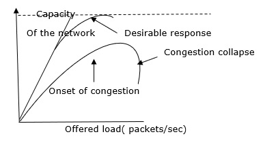
With too much traffic, performance drops sharply.
There are two types of Congestion control algorithms, which are as follows −
- Leaky Bucket Algorithm
- Token Bucket Algorithm
Leaky Bucket Algorithm
Let see the working condition of Leaky Bucket Algorithm −
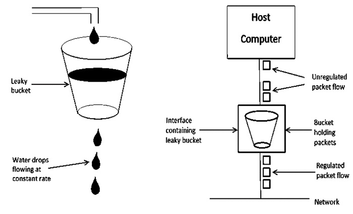
Leaky Bucket Algorithm mainly controls the total amount and the rate of the traffic sent to the network.
Step 1 − Let us imagine a bucket with a small hole at the bottom where the rate at which water is poured into the bucket is not constant and can vary but it leaks from the bucket at a constant rate.
Step 2 − So (up to water is present in the bucket), the rate at which the water leaks does not depend on the rate at which the water is input to the bucket.
Step 3 − If the bucket is full, additional water that enters into the bucket that spills over the sides and is lost.
Step 4 − Thus the same concept applied to packets in the network. Consider that data is coming from the source at variable speeds. Suppose that a source sends data at 10 Mbps for 4 seconds. Then there is no data for 3 seconds. The source again transmits data at a rate of 8 Mbps for 2 seconds. Thus, in a time span of 8 seconds, 68 Mb data has been transmitted.
That’s why if a leaky bucket algorithm is used, the data flow would be 8 Mbps for 9 seconds. Thus, the constant flow is maintained.
Token Bucket Algorithm
The leaky bucket algorithm enforces output patterns at the average rate, no matter how busy the traffic is. So, to deal with the more traffic, we need a flexible algorithm so that the data is not lost. One such approach is the token bucket algorithm.
Let us understand this algorithm step wise as given below −
Step 1 − In regular intervals tokens are thrown into the bucket f.
Step 2 − The bucket has a maximum capacity f.
Step 3 − If the packet is ready, then a token is removed from the bucket, and the packet is sent.
Step 4 − Suppose, if there is no token in the bucket, the packet cannot be sent.
Example
Let us understand the Token Bucket Algorithm with an example −
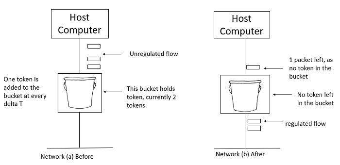
In figure (a) the bucket holds two tokens, and three packets are waiting to be sent out of the interface.
In Figure (b) two packets have been sent out by consuming two tokens, and 1 packet is still left.
When compared to Leaky bucket the token bucket algorithm is less restrictive that means it allows more traffic. The limit of busyness is restricted by the number of tokens available in the bucket at a particular instant of time.
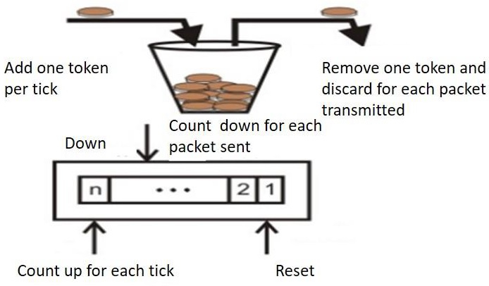
The implementation of the token bucket algorithm is easy − a variable is used to count the tokens. For every t seconds the counter is incremented and then it is decremented whenever a packet is sent. When the counter reaches zero, no further packet is sent out.
This is shown in below given diagram −


No comments:
Post a Comment