Comparator in Digital Electronics
Definition
A comparator is a digital combinational circuit that compares two binary numbers and identifies their relationship. The outputs indicate whether the numbers are equal, or which one is greater or smaller.
In short, the purpose of a comparator is to check the magnitudes of two binary inputs and generate logical outputs such as:
- A > B
- A = B
- A < B
Example
Consider two 3-bit binary numbers:
- A = A2 A1 A0
- B = B2 B1 B0
The two numbers are said to be equal if all corresponding bits are the same, i.e., A2 = B2, A1 = B1, and A0 = B0.
A general comparator produces three outputs:
- L → (A < B)
- E → (A = B)
- G → (A > B)
Types of Comparators
Comparators are classified based on the number of bits they compare:
-
1-Bit Comparator
-
2-Bit Comparator
-
4-Bit Comparator
1-Bit Comparator
A 1-bit comparator compares two binary inputs A and B. The three possible outcomes are:
- If A = 0 and B = 0, or A = 1 and B = 1 → A = B
- If A = 0 and B = 1 → A < B
- If A = 1 and B = 0 → A > B
The block diagram of a 1-bit magnitude comparator is shown in the following figure −
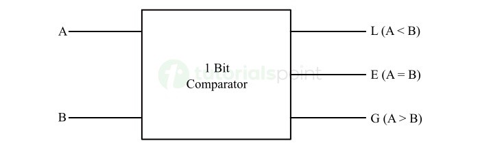
Truth Table:
| Inputs | Outputs | |||
|---|---|---|---|---|
| A | B | L (A < B) | E (A = B) | G (A > B) |
| 0 | 0 | 0 | 1 | 0 |
| 0 | 1 | 1 | 0 | 0 |
| 1 | 0 | 0 | 0 | 1 |
| 1 | 1 | 0 | 1 | 0 |
- A = B → E = A'B' + AB = A ⊙ B
- A < B → L = A'B
- A > B → G = AB'
The logic circuit diagram of the 1-bit magnitude comparator is shown in the following figure.

It consists of two AND gates, two NOT gate, and an XNOR gate.
2-Bit Comparator
For two binary numbers:
- A = A1 A0
- B = B1 B0
We can understand the operation of the 2-bit magnitude comparator with the help of its truth table given below −
| Inputs | Outputs | |||||
|---|---|---|---|---|---|---|
| A1 | A0 | B1 | B0 | L (A < B) | E (A = B) | G (A > B) |
| 0 | 0 | 0 | 0 | 0 | 1 | 0 |
| 0 | 0 | 0 | 1 | 1 | 0 | 0 |
| 0 | 0 | 1 | 0 | 1 | 0 | 0 |
| 0 | 0 | 1 | 1 | 1 | 0 | 0 |
| 0 | 1 | 0 | 0 | 0 | 0 | 1 |
| 0 | 1 | 0 | 1 | 0 | 1 | 0 |
| 0 | 1 | 1 | 0 | 1 | 0 | 0 |
| 0 | 1 | 1 | 1 | 1 | 0 | 0 |
| 1 | 0 | 0 | 0 | 0 | 0 | 1 |
| 1 | 0 | 0 | 1 | 0 | 0 | 1 |
| 1 | 0 | 1 | 0 | 0 | 1 | 0 |
| 1 | 0 | 1 | 1 | 1 | 0 | 0 |
| 1 | 1 | 0 | 0 | 0 | 0 | 1 |
| 1 | 1 | 0 | 1 | 0 | 0 | 1 |
| 1 | 1 | 1 | 0 | 0 | 0 | 1 |
| 1 | 1 | 1 | 1 | 0 | 1 | 0 |
Conditions:
Equal (A = B):
E = (A1 ⊙ B1)(A0 ⊙ B0)Less Than (A < B):
L = A1'B1 + (A1 ⊙ B1)A0'B0Greater Than (A > B):
G = A1B1' + (A1 ⊙ B1)A0B0'
The following figure shows the logic circuit diagram of the 2-bit magnitude comparator −

4-Bit Comparator
For two binary numbers:
- A = A3 A2 A1 A0
- B = B3 B2 B1 B0
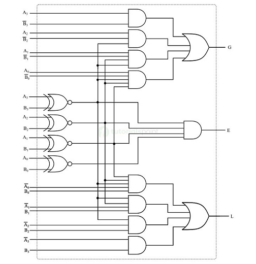
Equal Condition:
E = (A3 ⊙ B3)(A2 ⊙ B2)(A1 ⊙ B1)(A0 ⊙ B0)
Less Than Condition:
L = A3'B3 + (A3 ⊙ B3)A2'B2 + (A3 ⊙ B3)(A2 ⊙ B2)A1'B1 + (A3 ⊙ B3)(A2 ⊙ B2)(A1 ⊙ B1)A0'B0
Greater Than Condition:
G = A3B3' + (A3 ⊙ B3)A2B2' + (A3 ⊙ B3)(A2 ⊙ B2)A1B1' + (A3 ⊙ B3)(A2 ⊙ B2)(A1 ⊙ B1)A0B0'
The logic circuit implementation of the 4-bit magnitude comparator is shown in the following figure −
Applications of Comparators
-
Used in arithmetic logic units (ALU) of microprocessors.
-
Employed in zero-crossing detectors in control circuits.
-
Used in analog-to-digital converters (ADCs).
-
Helpful in voltage level detection and signal conditioning.
-
Applied in automation and digital communication systems.
Conclusion
A comparator is an essential combinational circuit that checks whether two binary numbers are equal or determines which one is greater. Depending on bit size, comparators can be designed as 1-bit, 2-bit, or 4-bit circuits, or implemented using ICs like 7485. They play a vital role in decision-making processes within microprocessors, digital systems, and control applications.


No comments:
Post a Comment